
In part two of our series on keeping backflow preventers out of basements, we learned that a 3” reduced pressure zone backflow assembly can be relied upon to fill a 12 X 12 mechanical room to its ceiling in about one hour. Of course, that’s if the walls hold. Not likely.
We have some rare photographs of an actual RPZ event. I say rare, because such pictures almost never reach the public domain. Virtually NO ONE wants such pictures to surface. Not the property owner, not the manufacturer, certainly not the designers or installers, and most troubling, not the water authority and building authority due to the perceived violation of the public trust. This mechanical room flood caused just over $1M of damage.
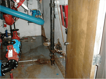
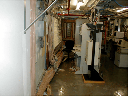
This first image shows this Wilkins 375 4” RPZ valve in a typical mechanical room setup. Note the 4” floor-drain to the right. One day (or more likely, one evening) this Wilkins 375 commenced to behaving in a manner consistent with its design. It began dumping huge volumes of water. The sudden water flow and volume moved the wall (behind the door) off of its stud and into the next room, which happened to be a telephone and low-voltage wiring room. This room is the second image.
Through the legal magic of something called the subrogation clause, the casualty insurance carrier sought recovery from all the usual suspects including the engineer, architect, contractor, subcontractor, and even the most recent backflow preventer tester.
Ironically, only the tester was fully exonerated. He showed his annual test record, a test that had been completed some three months prior, indicating proper working order. This reveals a fundamental misunderstanding of what these systems are designed to do. There is a false assumption that floods only occur when the backflow preventer fails to perform as designed. Sadly, the best way to ensure an indoor flood when that perfect storm occurs is to maintain the assembly properly. Let me say it another way. Just as Dragons start fires when they cough, RPZs are designed to perform a catastrophic release of water when their check valves fail or are blocked. It’s what they do.
While the details of who paid what were not made public, we do know that the property insurer was made whole by one or more of the listed defendants.
So if these things are designed to dump water, and you are determined to place it inside a building in a mechanical room, then drain capacity is the issue. Right?
The graph shows the manufacturer-provided Relief Valve Discharge Rate chart for the aforementioned Wilkins 375. It shows what that assembly will release in the perfect storm at various pipe sizes and at various pressures. I’ve picked out a rational overnight pressure of 85 PSI and drawn a red line. Given the fact that we are considering a 4-inch assembly, we focus on the curve
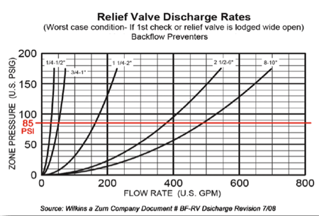
labeled “2½ - 6 inch”. That assembly and pressure combination will dump approximately 375 gallons per minute.
“But wait,” you say, “We have a drain!” Yes. Let's factor in the drain. According to EngineeringToolbox.com, a 4-inch drain system installed with a 1% grade of decent will clear as much as 93 gallons of clean water per minute. So if we are dumping at 375 GPM and we are draining at 93 GPM, then we’re flooding at a rate of 282 GPM! That’s about 100 gallons more than the 3” assembly in the video. Remember when I said the pipe sizes represented an order of magnitude increase rather than mere degrees? Rough calculations infer that if this mechanical room is of comparable size, then it would have filled to the ceiling in about 38 minutes had the walls held.
This intel was all given much more credibility in the summer of 2014 when David DeBord, the education chair of the American Society of Plumbing Engineers published a white paper on the subject. DeBord uses the Watts relief valve tables and a constant pressure of 65 PSI. He does the math including typical drain systems and comes up with what he calls net Flood rates of 219 GPM for the 2½- and 3-inch models, and a Flood rate of 482 GPM for anything larger. He goes on to conclude that with respect to indoor reduced pressure backflow preventer installations, “…the floor drain capacities of RPZs of 3-inch diameter and higher are likely to be cost-prohibitive due to the necessary pipe diameter and fall rates.”
Keep the RPZs out of the Basement
Plumbing engineers can design elaborate and expensive 8-inch drain systems all the way to the sewer, or put RPZs outside. To keep our drinking water safe and to prevent contamination, your backflow prevention device should be outside and above ground. This significantly decreases the risk of cross-connections.
The type of backflow preventer you have does not matter as much as where you install it. Whether it’s for an irrigation system, fire hydrant, sprinkler system-any water system with a water supply line, housing it (and the water meter) in an outdoor enclosure makes it easier to reach the test cocks and shut-off valves.
The safest place for your backflow preventer installation is in an above-ground enclosure that is outside. Our guide “Trends in Backflow Preventer Installation” can show you some of the more common installation locations and the risks you take when you install a backflow preventer inside.
.jpg?width=206&name=MadeInUSA-Icon%20(1).jpg "MadeInUSA-Icon (1)")
