
More often than not, water jurisdictions lack the standard details that engineers and contractors need to install backflow preventers properly and in the most advantageous way possible.
Some engineers may actively search for details specific to their respective jurisdiction; others may not have time to investigate. After all, time is money, especially when it comes to commercial and industrial development.
As a result, engineers default to whatever approach was done before, such as installing backflow preventers in below-grade vaults or inside a building.
These methods might have worked in the past, but industry experts increasingly advise against below-grade installation due to the numerous health and safety risks they pose to the public (i.e., compromised drinking water) and utility technicians' safety. Standards change for a reason — to accommodate better mechanical performance, financial investments, overall safety and maintenance management.
If your jurisdiction or city lacks a detailed set of standards that reflect the nuances of modern-day best practices, it's time to create one. We've worked with many water jurisdictions across the U.S. and want to help yours do the same.
A set of standard details should take the following into consideration.
Enclosure Placement for Ideal Backflow Prevention

While most water meters are installed in a public right-of-way, backflow preventers are installed inside the property line. Backflow preventers should be installed as close as possible to the meter. In some cases, design teams can apply for an easement grant from the state that permits the installation of the water meter and backflow preventer in a single above-ground enclosure.
Document the following in the standard details:
-
Maximum allowable distance from the curb or right-of-way to the meter (typically 20 feet).
-
Maximum allowable distance from the curb or right-of-way for the backflow preventer (typically 100 feet).
-
Water tap location notes suggesting water tap, meter and backflow should not be placed to obstruct the view of the proposed building or block vehicle sightlines.
EXAMPLE NOTE FOR STANDARD DETAILS:
ALL BACKFLOW PREVENTION DEVICES SHALL BE INSTALLED IN AN ABOVE-GROUND ENCLOSURE, IMMEDIATELY ADJACENT (I.E. AS CLOSE AS PRACTICABLE) TO THE DISCHARGE SIDE OF THE METER.
Backflow Prevention Assembly Installation
The type of building and its respective hazard level will determine the type of backflow prevention device required. Document the following details per hazard-level application:
-
Approved backflow preventer model. Most jurisdictions require USC approved backflow assemblies.
-
Premise isolation - 2 ½” through 12”
-
Backflow prevention assembly designs - Horizontal and N-pattern
-
Enclosure type - Specify ASSE 1060. This standard outlines requirements for freeze protection, drainage, structural integrity and secure access. Many municipalities now mandate Class I ASSE 1060 enclosures for high-risk or cold-weather installations to ensure reliable protection of the potable water system.
Fire Sprinkler and Domestic Water Systems Standard Installation Details
A complete set of standard details for above-ground enclosures should include the following.
-
Fire lines - 4” through 12”
-
Small domestic service - ¾” through 2”
-
Large domestic service - 2 ½” through 12”
-
Single or combined service taps
These details are important because backflow prevention assemblies protect drinking water by stopping contaminated water from reversing into potable water systems. Negative pressure changes from irrigation systems or fire protection systems often lead to backflow and cross-connections. Devices like double-check valves and RPZ assemblies help ensure water systems remain safe by preventing pollutants from entering the public water supply.
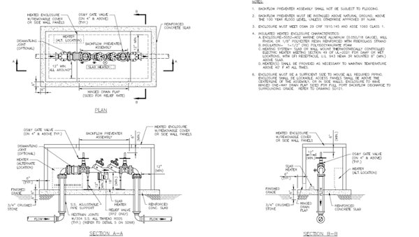
Enclosure Clearance Details
Internal clearances are also an important consideration. With removable access panels, the meter, control valve and backflow assembly are immediately accessible to the person performing testing or maintenance. Clearances required for a below-grade vault are no longer needed, which keeps the enclosure size smaller.
The standard details should provide the following internal clearances:
-
Top of the backflow prevention device to the roof of the enclosure
-
Bottom of backflow prevention assembly body or relief valve to the concrete slab
-
Distance from backflow preventer to enclosure walls
-
Length of straight pipe before and after the meter
Note: Some standard details drawings will show different clearance requirements on the side of the backflow preventer that has the test cock versus the opposite side of the backflow device. The side that does not have the test cock can be much closer to the enclosure wall.
Exterior Clearances
Adequate clearances in and around enclosures are important for routine maintenance and testing. A clearance from the exterior of the enclosure to adjacent landscaping should be noted.
Location of Enclosure Access Panels
The location of removable access panels will depend on the layout of the backflow preventer and meter. Consider how utility crews prefer to access the meter or backflow preventer. For example, some utility crews prefer to use a boom truck and removable roof panels to allow for access from above.
Document the following:
-
Number of removable access panels
-
Panel location with proximity to equipment
-
Panel size
-
Locking mechanism
EXAMPLE NOTE:
1. ENCLOSURE ACCESS PANELS SHOULD BE LOCATED TO ACCESS GATE VALVE HAND WHEELS, METERS AND BACKFLOW TEST COCKS; 2. ROOF SHOULD BE REMOVABLE FOR EQUIPMENT ACCESS.
Enclosure Drainage
An enclosure with a backflow preventer must include a water drainage system. If an event triggers an RPZ backflow preventer to discharge 300 gallons of water per minute, the drain needs to be large enough to adequately empty that water without compromising the public water supply. Include a requirement that the enclosure must include a hinged drain flap sized for the maximum relief valve rate.
EXAMPLE NOTE:
1. BACKFLOW PREVENTER ASSEMBLY SHALL NOT BE SUBJECT TO FLOODING. 2. BACKFLOW PREVENTER MUST BE INSTALLED ABOVE NATURAL GROUND, ABOVE THE 100-YEAR FLOOD LEVEL, UNLESS OTHERWISE APPROVED BY WATER UTILITY.
Even with a clear set of guidelines, it's important to remember that standard details will vary between jurisdictions. In addition to the information in this post, be sure to reference state regulations, local codes and product manufacturer recommendations.
Get the Guide To Prevent Potential Contamination
We've created five free templates, available in CAD and PDF formats, to help you modernize your standard details. Our guide makes it easy to upgrade your backflow preventer installation with up-to-date, above-ground solutions, ASSE 1060 compliance tips, and real examples from cities that have already raised the standard.
Download the free guide and simplify your next project.

.jpg?width=206&name=MadeInUSA-Icon%20(1).jpg "MadeInUSA-Icon (1)")
